Charge Air Cooler

Charge Air Cooler

The charge air cooler is known as the heat transferred in the engine-mounted heat exchanger . An charge air cooler is present on nearly all turbocharged engines. Its job is to remove the heat added to the incoming combustion air during its compression in the turbocharger. In this manner the charge air cooler simultaneously decreases the air temperature (to limit detonation) and increases the air density (a denser air/fuel charge enables greater power from a given engine displacement). Some engines may use a two-stage charge air cooler, an arrangement that runs the high temperature air first through a heat exchanger stage on the high temperature jacket water cooling circuit, then the same air is passed through a second stage on the lower temperature auxiliary circuit, improving performance of the charge air cooler. For such arrangements, two values are displayed in the engine technical data, one for each stage of the charge air cooler.

Single Circuit or Combined Circuit Cooling

Many engines use multiple cooling circuits. A single circuit cooling system may be found on a naturally aspirated (NA) engine, with no turbocharger and thus no charge air cooler to be placed on a separate circuit and a  turbocharged engine that cools the charge air cooler with jacket water (a jacket water aftercooled, or JWAC engine) also does not require a separate circuit since the heat loads use a common coolant flow. A combined circuit arrangement can be created by operating the jacket water system as a closed loop that is cooled by the charge air cooler flow. 

In isolating the jacket coolant, only one external cooling flow results.
Both the single circuit and combined circuit configurations produce a very simple cooling system setup. With all heat loads on a common circuit these configurations require only one coolant path to the external cooler, and thus can use a single-core cooler for the external portion of the circuit.

Separate Circuit Cooling

The most commonly seen configuration for turbocharged engines is the separate circuit arrangement, sometimes abbreviated as SCAC for “separate-circuit aftercooled.” In a separate circuit system, the charge air cooler is moved to a circuit distinct from that of the jacket water, which allows the two circuits to be regulated to different temperatures. Running the charge air cooler at a much lower temperature than the jacket water allows the intake charge temperatures to be lowered. The greater air density and reduced charge temperature that result both contribute to enabling higher engine power levels. Separate-circuit cooling is a necessity on gas engines. The lower temperature of the air-fuel mixture delivered to the cylinders is essential to avoiding detonation, one of the key limiting parameters for gas engine performance.

The separate circuit configuration does require one circulating pump, one thermostat, and one external cooler core for each circuit. If the engine shown above as a combined circuit arrangement were reconfigured to a separate-circuit configuration.

AKJ offer an array of charge air cooler designed to meet your product needs. At AKJ, we can solve all the needs of our customers and solve all the customization problems.

Air-to-Air Aftercooling (ATAAC)

A special case of separate circuit cooling seeks to use the best properties of liquid- and air-cooled systems on the same engine. The engine’s jacket water system is retained as it is found on other separate-circuit configurations, but the engine-mounted, liquid-cooled charge air cooler is replaced with a direct air-to-air heat exchanger, typically installed off-engine. This is done in instances where high ambient air temperatures are expected to limit the ability to achieve the required temperature of the coolant provided to the engine’s charge air cooler. By eliminating the liquid coolant circuit, one intermediate step of the heat exchange is removed. This allows only one step of temperature difference (approach temperature) instead of two, allowing the combustion intake air to be cooled to a temperature much closer to the ambient air temperature than would be possible with the liquid-cooled circuit.
AKJ offer an array of charge air cooler designed to meet your product needs. At AKJ, we can solve all the needs of our customers and solve all the customization problems.

Charge air cooler Condensation and Hot Shutdown Protection

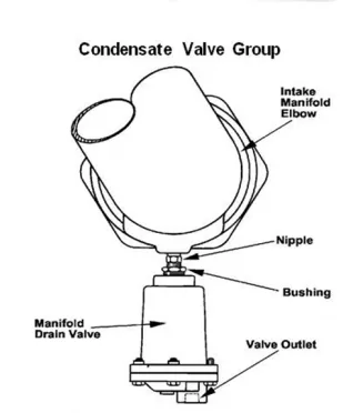
Humid intake air is not unusual for many climates, and in such conditions, cooling the airflow into the engine can result in a significant amount of water condensing in the air path of the charge air cooler core. The relatively low cooling temperatures further increase the potential for condensation, necessitating the inclusion of provisions to remove water from the charge air cooler core and piping in the design. For example, a G3516 LE Engine operating in a 32°C (90°F) application may produce up to 114 liters (30 gallons) of water per day.

To facilitate easy drainage, the intake air should enter the bottom of the core on one side and exit from the top on the opposite side. This routing of the airflow maximizes the potential for condensation to collect across the entire core. An automatic drain valve should be installed on the bottom side of the core, opposite the entrance of the intake air, to enable the removal of water from the system. It is important to ensure that the drain valve has free movement and does not freeze in cold temperatures.

In addition to the drain valve, condensate traps should be installed in the intake piping near the engine intake manifold to capture any remaining droplets before the air enters the cylinders. The design of a condensate trap typically involves forcing the airflow to quickly change direction, causing the heavier water droplets to be thrown into a trap wall where they are collected and drained through a float valve. It is crucial to size and design the condensate trap in a way that its pressure drop is not excessive, considering all components of the air path.

What causes charge air cooler failure?

Charge air coolers often fail between the turbo hose and the unit or between the intercooler and the engine downstream . A hose that becomes loose around the couplings or has a hole in it will cause a drop in pressure of the compressed air.

Scroll to Top